Autonomous TwizyLine

To carry out the TwizyLine project, we have designed and implemented a whole system that can be coupled to a vehicle to give it level 4 autonomous vehicle capabilities inside the TwizyLine car parks. We have performed an analysis of the optimum technologies for the project, its cost, and the elements available on the market, studying their interconnection and their viability in the project. All the technology mounted on the vehicle has been designed so that the vehicle can circulate autonomously and safely at 5km/h inside the TwizyLine enclosures.

Processing Units

Two new ECUs (Electronic Controlled Units) have been installed and programmed to carry out all the necessary tasks inside the vehicle. We have called them Communication Module and Control Module; each one performs specific tasks

Communication Module

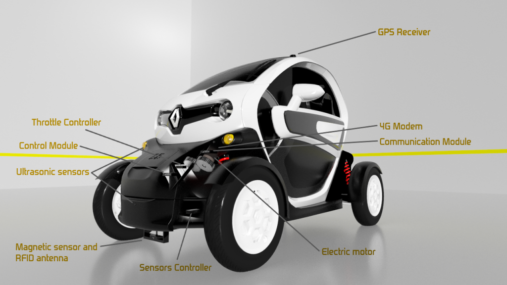
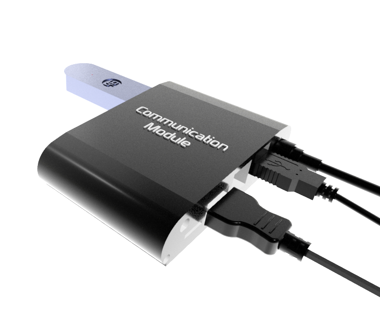
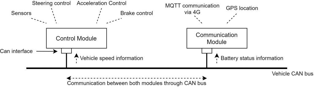
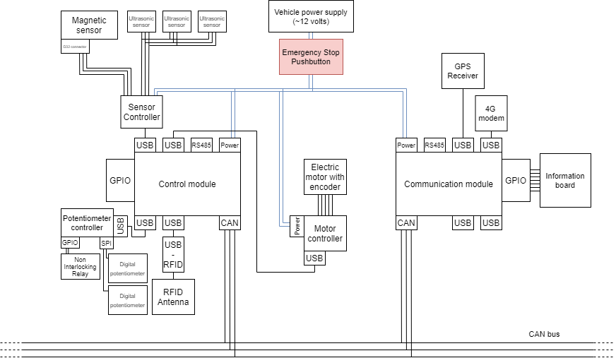
· Monitors the state of the vehicle’s battery and its location, thanks to a GPS receiver connected to it.

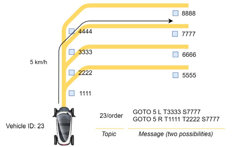
· Manages communication with the back-end, receiving orders and giving information about the state of the vehicle through MQTT. To achieve this communication, a 4G modem is connected to it.

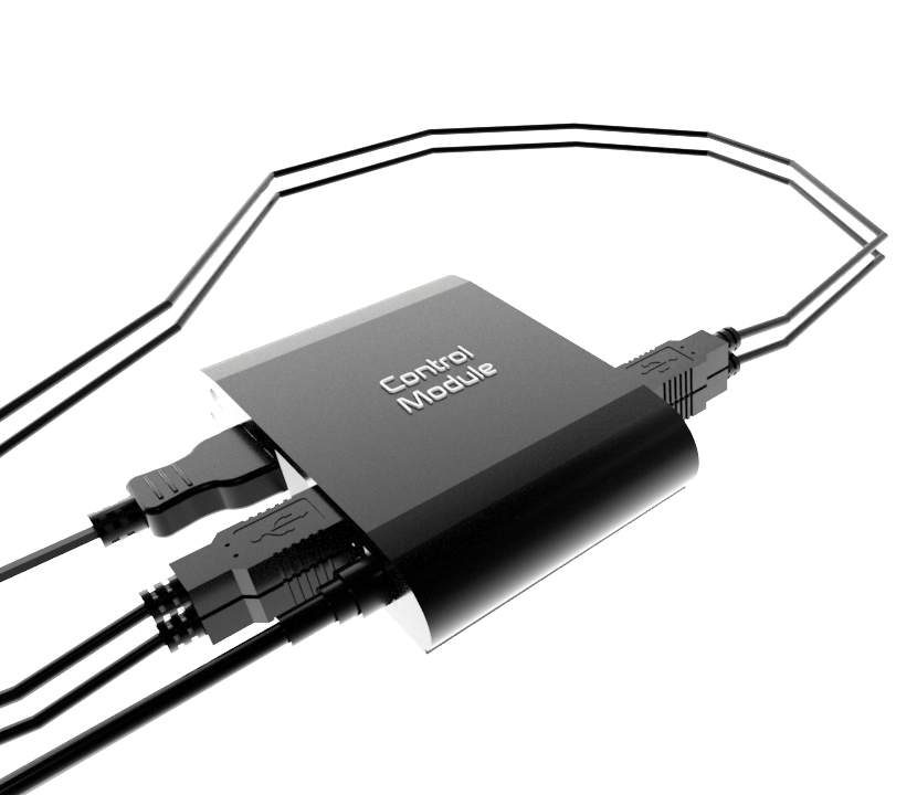
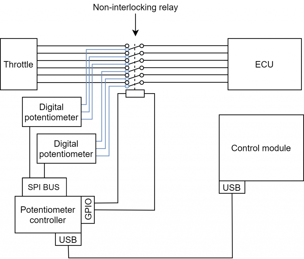
· Controls the Control Module.

Control Module

· Receives orders and reports possible errors to the Communication Module.

· Performs vehicle control tasks, interpreting the information from the sensors and controlling the installed actuators.

Both ECUs are connected to the vehicle’s CAN bus. In this way they receive information about the vehicle’s status, and, at the same time, they can communicate between them by injecting new CAN frames. This involved the development of a new CAN messaging that allows both modules to be synchronised and to properly manage errors between them, guaranteeing security.

Sensors

The vehicle incorporates a series of sensors to achieve the correct guidance of it inside the TwizyLine car parks.

Also, the vehicle is equipped with a Sensor Controller, based on an Arduino Nano, to control the sensors and receive their information. This is connected to the Control Module in order to send it the necessary information.

Ultrasonic Sensor

To ensure safety inside the TwizyLine car parks, the vehicle is equipped with 3 ultrasonic sensors. These sensors allow the vehicle to detect other vehicles, obstacles, or people in front of it. In this way the vehicle can adapt its speed (working as an Adaptive Cruise Control system) or stop if necessary. These sensors act in a synchronized way avoiding interference between them (cross talk). They cover a range of 60° and reach up to 7 metres, which is ideal for safe vehicle guidance. Thanks to these ranges, the vehicle can predict an accident and reduce its speed when it detects that an obstacle is going to be in its path. In addition, the sensors are redundant for added safety.

Magnetic Sensors and RFID Antenna

The vehicle is guided by a magnetic band placed on the floor that indicates the path it must follow. To be able to follow this band, the vehicle incorporates a magnetic sensor (donated by the company Asti) capable of detecting it and determining the position of the vehicle with respect to the tape. 

The use of this technology brings many advantages. It is a very reliable guiding method as it is not affected by the presence of dirt or rain and can be buried under the ground to preserve its integrity over time. At the same time, it provides a lot of flexibility as it can be easily assembled and disassembled at any time. In this way new routes can be easily established. This technology is widely used today in industrial environments and is therefore highly tested.

In the TwizyLine car parks there are points where a vehicle must behave in a specific way, either by stopping or following a specific route at a fork. RFID technology is used to achieve this. The car parks include a series of RFID tags arranged on the ground and the vehicle is equipped with an RFID antenna capable of detecting them. Once the vehicle enters the car park, the back-end informs it what to do when it detects a specific RFID. In this way the back-end can monitor the location of the vehicle inside the car park and specify which route it should follow.

Actuators

In order for the vehicle to be controlled by the Control Module we have added several systems inside it. In this way, the Control Module, with the information from the sensors and that acquired via the CAN-bus, will be able to control the vehicle autonomously.

Longitudinal Control

To carry out the longitudinal control of the vehicle we have focused on the control of the accelerator. We have developed a Throttle Controller for this purpose. When the vehicle is in autonomous mode, it bypasses the connection between the accelerator and the vehicle systems. In this way, the controller takes over control of the accelerator. This controller is connected to the Control Module, thus, the module is able to control the acceleration of the vehicle when necessary.

Lateral Control

The lateral control of the vehicle has been carried out by coupling an electric motor (donated by the company Maxon) to the steering column of the vehicle. This motor is connected to a specific controller, which is then connected to the control module. More information about the installation of this device inside the vehicle can be found in the mechanical modifications section.

Diagram of the Elements Installed in the Vehicle

Scroll to top